Many people find that permanent magnets involve something very mysterious.
«What are permanent magnets used for?» is oftentimes the question we hear. Only very few know that permanent magnets have become an essential part of modern technology and that we all make use of what they have to offer on a daily basis. In our headphones or speakers, our smart phone, the electric drive in the electric car, electric bicycle, scooter, wheelchair, in wind turbines for generating power, just to name a few. In technology, permanent magnets are used in electrical and mechanical measuring devices, as acoustic transducers, electromagnetic converters, machine elements, and we take advantage of their magnetic force.
Today, permanent magnets have also become a vital component in medical applications, in biology and in nuclear physics. Because of their wide distribution and very affordable cost, neodymium magnets especially, which are also referred to as super magnets, are widely distributed in games and recreational items.
Despite their many potential uses, only a relatively small number of technicians have a sound understanding of the theory and practical application of permanent magnets. This may have to do with that the fact that, unfortunately, only very few universities and technical schools are able to convey knowledge and research about permanent magnets.
Basic Magnetic Terms
1. Magnetic Flux
Imagine the magnetic field surrounding magnetized permanent magnets as a room filled with magnetic lines of force. The lines of force extend from the magnet’s north pole and expand through the room in a large arc to the south pole. In doing so, every line of force creates its own circle.
The magnetic flux is the sum total of all lines of force.
The symbol indicating the magnetic flux is Φ (phi), and represents the entire number of a magnet’s lines of force.
The unit of the magnetic flux is:
1 Maxwell = 1 line of force
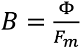
Φ = B ∗ Fm
Total magnetic flux= remanence in Gauss * area (cross section) magnet in cm2
2. Remanence
The stronger the magnetic effect of a magnetic field at any given location, the more dense one can imagine the progression of the lines of force there.
The remanence or induction is the density of the lines of force.
The symbol for remanence is B and stands for the number of lines of force that run vertically through a surface of 1 cm2.
One unit of remanence or induction is:
1 Gauss = 1 line of force per cm2 = 10-8 voltseconds/cm2
Remanence = (Total magnetic flux in Maxwell)÷(Surface in cm2, through which the magnetic flux exits)
3. Coercive force
To understand coercive force, imagine the resistance to demagnetization by an outer magnetic field. It is the durability to permanent magnets opposing a demagnetizing influence.
The symbol for the coercive force is the character Hc, which stands for the size of an outer field opposite to a permanent magnet, which is capable of pressing down the permanent magnet’s remanence to zero.
The unit for coercive force is:
1 Oersted ≅ 0,8 AW/cm (ampere windings per cm)
4. Magnetomotive force
Inside each permanent magnet, after it has been magnetized, is a magnetic voltage, which can be seen as the cause for why a magnetic field is generated in the space surrounding the magnet.
The magnetomotive force (MMF) is the sum total of the magnetic voltage or the total magnetic driving force of a permanent magnet, the effect of which is that the space surrounding the magnet is filled with lines of force.
The symbol for magnetomotive force is Θ (theta) and stands for the sum total of the existing magnetic voltage.
The unit of the magnetomotive force is:

1 Gilbert = 1 Oersted × cm ≅ 0,8 ampere windings
Magnetomotive force = coercive field strength ∗ length of the magnet in cm
5. Coercive field strength
The further out of the space the lines of force of a magnetic field are driven, the greater we can imagine the magnetic field strength to be.
The coercive field strength is the magnetic voltage per unit of length of a magnetic field.
The symbol for the coercive field strength is H and stands for the magnetic voltage or magnetomotive force, which is contained in 1 cm length of a permanent magnet.
The unit for coercive field strength is:

1 Oersted ~ 0,8 AW/cm (ampere windings per cm)

The link to the size of the ampere winding typically used in electricity theory is created as follows:
The magnetic voltage of a coil through which electric current flows is equal to the magnetic voltage of a permanent magnet. The magnetic current of a coil or its magnetomotive force is calculated based on the formula l * n / L = AW/cm, whereas I equals the flowing current in ampere, n the number of the wire’s windings and L the length of the coil in cm, resulting in the product ampere windings/cm.
6. Hysteresis loop
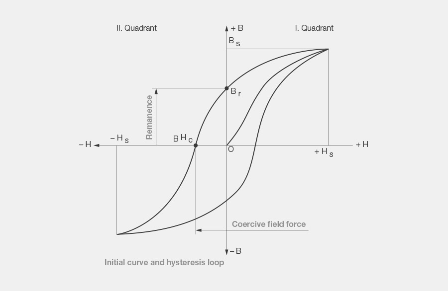
The hysteresis loop is the graphic representation of the behavior of a material in an outer magnetic field. For this purpose, the remanence B is entered in the ordinate and the coercive field strength H on the abscissa in a right-angle coordinate system. Now, the material from which the hysteresis loop is to be calculated is subjected to a gradually growing magnetic field. The remanence increases in the specimen as a result. If we enter this increase in the first quadrant of the coordinate system, the result is what is referred to as the initial curve, which at + HS (saturation field strength) reaches a saturation value typical for any ferromagnetic material. This saturation is also referred to as maximum induction.
If we now allow the field strength of the outer magnetic field to decrease, the remanence in the permanent magnetic material does not return to the initial curve. The inductive values are higher and while the outer magnetic field is fully shut off (H = 0) a finite value Br is retained. This is the remanent induction or the residual magnetism in the remanence point.
If the outer field is now reversed and if we allow it to increase this way, then remanence B will continue to decrease until it fully disappears in what is referred to as the coercivity point BHc (B = 0).
Modern materials from the group of rare earths create a deeper anchoring of the magnetic dipoles and are not reversed until a magnetic field is reached, which in some cases is several times higher JHc . This value is decisive for a resilience to demagnetizing magnetic materials in strong demagnetizing fields and temperature resistance, for example in electric motors. In order to calculate magnetic circuits, the value BHc is used.
While the magnetic field continues to amplify, B, now with an inverted sign, approaches a negative branch towards the first opposing saturation point. If we now repeat the entire process again with changed polarity, then B returns to the first saturation point on a path that is symmetric to the first curve. The loop closed this way is referred to as the hysteresis loop. The area that it encloses represents the energy that was converted into heat during demagnetization.
7. Demagnetization curve
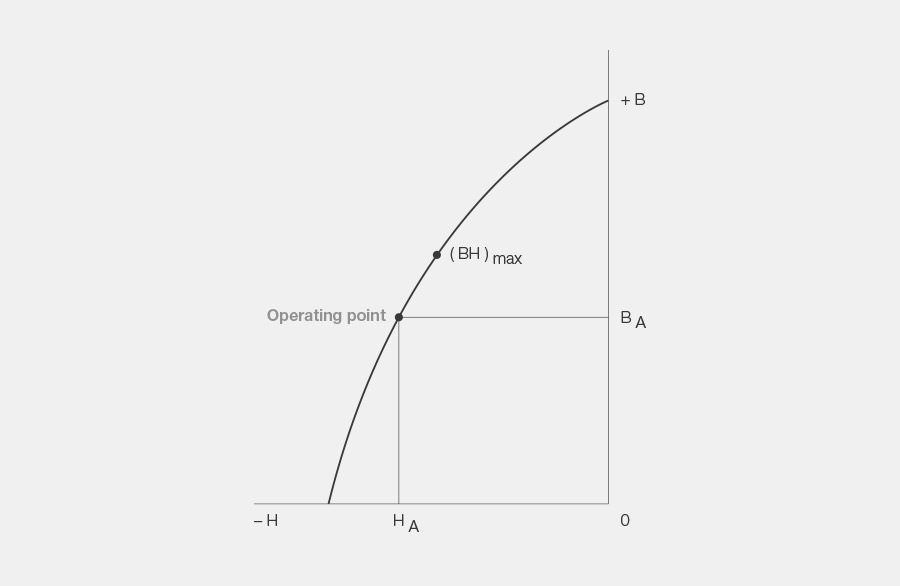
This characteristic curve that is exceptionally important for permanent magnets is an excerpt from the hysteresis loop. It shows the progression of B in the second quadrant for an increasing field strength opposite to the magnetizing. As a criterion for the quality of a magnetic material and for calculating permanent magnets, it is extremely important.
8. Operating point
The mechanics of how the operating point of a magnet adjusts itself is quite complicated. For practical purposes, the following qualitative explanation will suffice:
The location of a magnet’s operating point that was magnetized in a yoke or in a solenoid coil is found in remanence point Br after the outer magnetic field generated with the current is switched off. After opening the yoke or after the magnetizing pulse, an air gap is now created in the magnetic circuit, which until this point has been completely closed. Magnetic poles are now formed on the surfaces of the air gap. These poles “magnetize” the air gap, i.e. they emit a magnetic flux and build up a magnetic field in the air gap. At the same time, the magnet demagnetizes itself as far as necessary in order to build up the magnetic field, and does so depending on the length of the air magnet.
The magnetomotive force necessary to build up the field is generated by the mechanical energy that is needed to open the magnetic circuit, or in order to pull out the magnet from the yoke. This magnetomotive force has the effect that the magnet demagnetizes itself, because it is facing the opposite direction of the magnetization. This is why remanence B wanders from induction point Br on the demagnetization curve in direction H to a new point BA, the operating point, and its location depends on how far the magnetic circuit was opened and how large the coercive force of the magnetic material is. Its location can be influenced by selecting the magnet longer or shorter depending on the coercive force.
The operating point of a magnet on a demagnetization curve shows the current magnetic state. The remanent operating point BA and to coercive operating point HA correspond to the operating point.
9. (BH)max-point
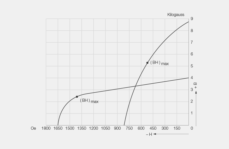
The (BH)max point is on the position of the demagnetization curve where the corresponding values for remanence and for coercive force are multiplied by each other, resulting in the largest product.
10. Energy product
This product is calculated based on the corresponding values for remanence and for coercive field strength, which can be read from the demagnetization curve. It shows the remanent energy of a magnetic material.
In order to properly utilize a magnetic material, it is expedient to design the magnetic circuit so that the magnet operates in the (BH)max point, because in doing so, the maximum energy is available in the air gap for a given volume of magnetic material.
The (BH)max-product indicates the maximum operating capacity of a magnetic material in relation to the spatial unit.
The symbol for the energy product is (BH)max and stands for the maximum product (BA * HA) of a magnetic material.
11. Flux leakage
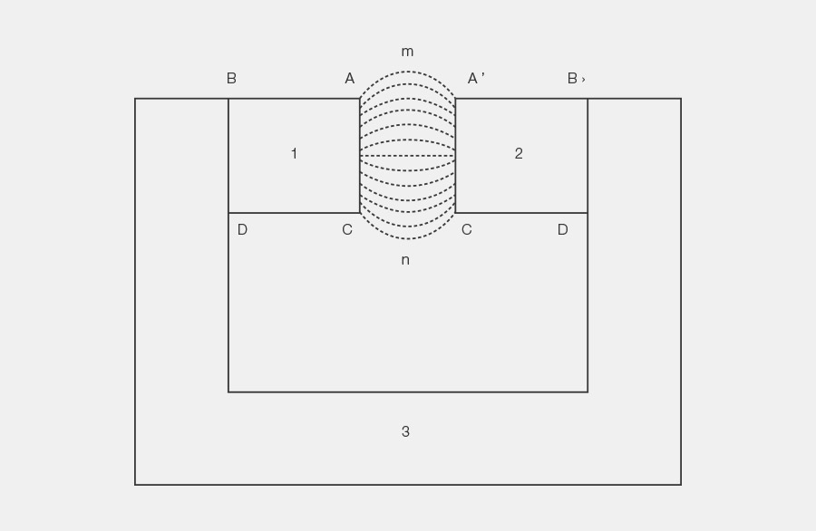
Most permanent magnets do not operate in the same operating point along their entire length. The entire magnetic flow only goes through the magnet in the neutral zone (halfway between the two poles). This entire magnetic flow is composed of the useful flow in an air gap and the inevitable flux leakage. If we want to allow a magnet to work along its entire length in the same operating point, this magnet must become thicker towards the middle in order to counteract the flux leakage. This is one reason why the sides are tapered on many horseshoe magnets.
However, in practical applications, we assume that the magnets work along their entire length in the same operating point, i.e. that they show the same magnetic flux everywhere. In most cases, this is exactly enough, however it requires that the scattering loss is considered in all calculations, designs and measurements.
12. Reluctance
The reluctance is the magnetic resistant of a magnetic circuit. It is the resulting value of all magnetic partial resistances of different units from which the magnetic circuit is composed. The reluctance value is needed in order to determine the magnetic flux, which is required in a specific part of a magnetic circuit, for example in an air gap. The symbol for reluctance is R.

13. Calculating permanent magnets
When calculating permanent magnets, the assumption is preferably based on the specific reluctance or its reciprocal value, the specific permeance. The most difficult part of determining the specific reluctance or permeance is calculating the scattering and potential losses. There are in fact formulas that can be used to calculate the most common magnetic circuits, yet these formulas are either much too complicated, or the calculations based on simplified formulas only result in approximated values. So, it does not make any sense to attempt to exactly calculate a magnetic circuit to five digits after the decimal point if in that case only approximately calculated factors are available for scattering and potential loss. Even for a supposedly exact calculation of these factors, the calculations will inevitably have to be verified with measurements on a model.
What can generally be stated is that the scattering loss factor ρ1 (rho1) is between 2 and 10 in most cases. The given cross-section of the useful air gap must be multiplied by this value to compensate for the inevitable scattering losses of every magnetic circuit. The potential loss factor ρ2 (rho2) is much smaller and is typically between 1.1 and 1.5. The length of the given useful air gap must be multiplied by this factor in order to compensate for the losses at the magnetomotive force (MMF) that arise as a result of the bending lines of force and at the joints of the magnetic circuit.
The scattering loss factor is referred to as σ (sigma) in modern literature, while the potential lost factor is referred to as τ (tau).
We differentiate between σr of σ. The practical scattering factor is σr = Φi ÷ Φen.The total scattering factor is σ = Φi ÷ Φe. For this the Φen includes the net flux in the air gap, Φi the flux in the magnets and Φe the total flux that crosses the air gap.
Because it is so difficult to calculate the exact loss factors, permanent magnetic circuits should not be designed based on calculated values alone. Experience values and measurement results based on test models must also be considered. Because of these difficulties, the design of permanent magnetic circuits should not be a purely mathematical task, but should just as much be an art form, which, by the way like all art forms, requires talent and experience.
Modern computer-aided calculation programs may very reliably calculate defined permanent magnet systems in the set-up phase. However, it will become more difficult for systems that are set up with multi-pin magnets or magnets made up of several different poles.
The calculation programs are not yet able to suggest the basic set up and design of a magnet system. The planned magnet system must still be designed for a specific purpose or specific properties.
Why so many magnetic alloys?
The many different nuances of isotropic, anisotropic and crystal-oriented magnetic materials would surely not have been produced if there had not been a need for them. For example, a magnet should only show an absolute minimum volume, or it must drive magnetic flux through a large air gap, or it must be able to withstand high temperatures, or it should be very affordable, or it must be possible to magnetize it on many poles along the circumference, or it must be able to withstand demagnetized fields. All of these requirements can only be met using a magnetic material coordinated for the intended purpose.
Magnetic formulas
1. BIOT-SAVART law
A current-carrying conductor generates a magnetic field on any point P is outside of the current thread. In integral form, it applies to an infinitely long stretched conductor:

I = current in amperes, a = distance from point P to the conductor in cm, μr = relative permeability
2. LAPLACE’s law
A current-carrying conductor with a length L in the field of other current-carrying conductors or permanent magnets s subjected to a force F.

I = current in amperes, L in cm, B = induction in Gauss apply
Valid for B perpendicular to L, whereas L is in turn perpendicular to L and to B. Here, the left-hand rule applies: B in index finger direction, current direction equals the middle finger, force equals the thumb.
3. KIRSCHOFF’s rules
In every point of a magnetic circuit, the sum total of the incoming flux ∑Φe equals the sum total of the outgoing flux ∑Φa
In a closed magnetic system, the sum total of the magnetic reduced voltage (Reduced voltage=Φ x R, i.e. flux times reluctance) is equal to the sum total of the effective magnetomotive forces in the system.
At times, these rules are also referred to as Houston’s rules for magnetic circuits.
4. Reluctance formula
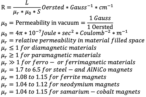
A prismatic structure of length L and cross-section S has a magnetic resistance or reluctance R.
The following applies:
5. R.K. Tenzer formula
The practical scattering factor σ_r of a permanent magnetic circuit based on the “symmetrical magnetic system” pattern is approximated using the following formula:

6. Differential equation by C. Schick
For the total scattering factor σ of an ideal permanent magnetic circuit based on the “symmetrical magnetic system” pattern, the following differential equation applies:

x=Length from air gap, K=Constant
Φe=Flux in volume A m A^’ C^’ n C
Φi=Flux in the magnets
7. Formulas by C. Schick
The following relationships apply to the total scattering factor σ of a permanent magnetic circuit based on the “symmetrical magnetic system”:

8. Transformation formula by C. Schick
The following relationship exists between the total scattering factor σ and the practical scattering factor σr, which applies to the ideal magnetic circuit:

9. Force formula
Between a magnet with a cross section S and a pole shoe made of soft iron that touch each other, what we have is a magnetic induction B, which can be assumed to be constant. The force that the magnet applies to pull the pole shoe can be calculated using the following formula:

F = Force in kg
B = Induction in Gauss
S = Surface in cm2
(If a magnet and pole shoe do not touch each other, what needs to be done is to first calculate the scattering factors in order to obtain a more accurate value for the induction).
10. S. Evershed criterion for static magnetic systems
In order to take full advantage of the given volume of magnetic material, operating point Ha, Ba of the magnetic system must be selected so that the product Ha * Ba equals the maximum possible product.
11. E.A. Watson formula
For steel magnets approximately the following relationships apply:
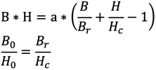
B0 and H0 correspond to the optimum operating point and a is a constant.
12. S. Earnshaw theory
In the field of other permanent magnets, a permanent magnet cannot be in stable equilibrium.
Magnets Units
| Designation | Abbreviation | Unit | Definition or equivalence |
| Length | L | Meter (m) | Basic unit |
| Time | t | Second (s) | Basic unit |
| Mass | m | Kilogram (kg) | Basic unit |
| Force | F | Newton (N) | 1 N = 1 kg ∗ 1 m/s2 |
| F | Kilopond (kp) | 1 kp = 9,81 N | |
| Work | E | Joule (J) | 1 J = 1 N ∗ 1 m |
| Performance | P | Watt (W) | 1 W = 1 J/1 s |
| Current | I | Amperes (A) | Basic unit |
| Voltage | U | Volt (V) | 1 V = 1 W/1 A |
| Magnetic Flux | Φ | Weber (Wb) | 1 Wb = 1 V ∗ 1 s |
| Φ | Maxwell (M) | 1 M = 10-8 Wb | |
| Magnetic Induction | B | Tesla (T) | 1 T = 1 Wb/ m2 |
| B | Gauss (G) | 1 G = 10-4 T | |
| Magnetomotive force | MMF | Ampere winding (AW) | 1 AW = 1A ∗ 1 Wdg. |
| Θ | Gilbert (Gb) | 1 Gb = 0,796 AW | |
| Magnetic field strength | H | Ampere winding/Meter (AW/m) | 1 AW/m = 1 AW/ 1 m |
| H | Oersted (Oe) | 1 Oe = 79,6 AW/m | |
| Reluctance | R | Ampere/Weber (A/Wb) | 1 A ∗ Wb-1 = 1 mho/s |
| Electric resistance | r | Ohm (n) | 1 Ω = 1 V/ 1 A |
| Electric conductance | G | Siemens (S) | 1 S = 1 Ohm-1 = 1 mho |
Length
Time
Mass
Force
Work
Performance
Current
Voltage
Magnetic Flux
Magnetic Induction
Magnetomotive force
Magnetic field strength
Reluctance
Electric resistance
Electric conductance
The Magnetic Materials and Their Creation
AlNiCo
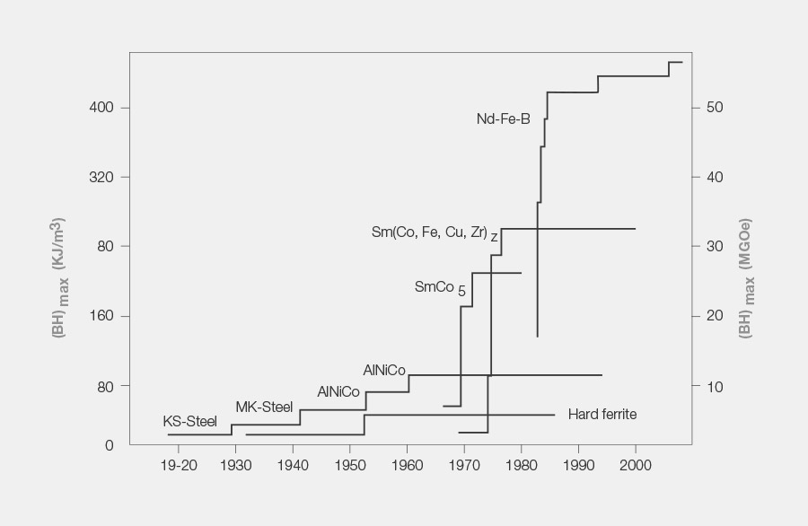
The first magnetic materials that were used in the industry originated in the 1920s. This magnet type is a cast steel alloy consisting of aluminum, nickel, cobalt and iron and is known under the designation AlNiCo. It was produced for the first time in England. One of the most important brand names was “Eclipse”.
Hard ferrite
During World War II, Germany was not allowed to import any steel alloy materials. This is why a new magnetic material category was invented during the German Reich, which was ferrite. The new material was produced by sintering iron oxide, a waste product from iron smelting, with the freely available heavy metals barium or strontium. The established magnet manufacturers in England referred to the material as “dirty magnets”, because in their view, its processing was a dirty one. From a technical perspective in the magnet industry, the new material was no revolution and was considered rather poor quality. Nonetheless, in the 1950s a triumph was celebrated, because the material could be produced at a much lower price point than other magnetic materials.
Plasto ferrite and plastic-bonded compounds
Shortly after the invention of hard ferrite, a new material was created, the flexible magnet.
It is created by embedding ferrite magnetic powder with a high filling ratio into a plastic matrix . The performance capability of the magnetic properties is reduced by around 30% as a result, yet this is exactly why the material was given preference in advertising and for warehouse signs.
The material also found its way into electric engine construction in injection form or as pellets. The material is designed as thermoset and, accordingly, it is hard and dimensionally stable. Specifically, it could be used to cast gears or to inject axles.
Samarium Cobalt
This material was invented in Switzerland in the late 1960s. The new Samarium Cobalt material allowed the industry to make a huge technological leap, because this magnetic material reached a magnetic performance that was several times greater than that of hard ferrite and AlNiCo. During the first ten years, the material was only used in special applications. Even today, this material is an important one in the industry thanks to its specific temperature behavior properties, in terms of its magnetic stability and its oxidation resistance.
Neodymium (super magnets)
Today, neodymium is the undisputed leader among magnetic materials. Here as well, its triumph was as a result of its excellent price-performance ratio. However, the material does have a few disadvantages: Because of the addition of the half-element boron, the alloy is unstable and some fiddling is required in order to produce application stable materials. If its performance as compared to all other magnetic materials were not so much better and the price were not so low, no one would us an alloy this unstable.
However, the drawback of this magnetic material is the source of the raw material and how it is refined. 97% of the world’s raw material mining takes place in China as does over 60% of material refining. As a result, the industry depends enormously on Chinese suppliers. What must also be considered is the contamination from radioactive by-products, which are created when extracting this rare earth. The damage to the environment could be huge, as was already the case in Malaysia several years ago. Another problem is that the magnetic material is primarily used for games and recreational products. Is it really worthwhile for China to exploit its resources and dump them cheap on the market?
The western world’s dependence is so great that the industry is already researching alternatives that would allow it to do without this magnetic material. This applies particularly to the automotive industry with respect to its electric engines. Tesla, the automotive manufacturer from the United States, makes direct use of permanent magnet free induction motors. European manufacturers, on the other hand, make use of synchronous motors equipped with permanent magnets.
Plasto neodymium
Just like the plasto ferrite, this substitute material was also developed as a flexible magnetic material in the 1990s. As compared to plasto ferrite, plasto neodymium achieves a ten times greater adhesion force.
Future of magnetic materials
In the near foreseeable future, no new magnetic material generation is expected. Current research is primarily focused on replacing hard to source raw materials and ways to optimally recycle magnetic material. The highly oxidizing rare earths cannot be easily extracted for recycling. This is why the focus must be on the ability to reuse the magnets. In the past, this approach was only successful in large generators used for wind turbines. Here, the large magnet segments are installed by way of mechanical screw connections so as to allow the magnet to be removed undamaged at a later time for reuse elsewhere.
Right now, a cold spray method is being developed in additive manufacturing. The NRC Research Institute in Canada expects that, as compared to sintered rare earths, the method will achieve a higher resistance and allow more complex configuration options as well as provide good magnetic values and higher corrosion resistance. In addition, system configurations combined with pole returns made of iron no longer need to be assembled or bonded.
Availability and development of magnetic materials
The main groups of magnetic materials are broken down into a groups of sub-varieties.
Reflected in these segments are mainly the development stages of each respective manufacturing option. The properties primarily aim to induce higher energy products (BHmax) as well as to increase remanence (Br) and the coercive force (Hcj). The energy content and the increased remanence are designed to increase the performance capability. For the coercive force (resistance), the objective is to improve or rather increase the application temperature and to sectorally demagnetize the magnets in electric motors, which is also referred to as footprint.
Magnetic Properties
AlNiCo
The AlNiCo magnets feature in particular the following properties:
- Temperature stability of 0.02% per °C
This is why AlNiCo magnets are ideally suited to achieve stabilized temperatures in weighing systems and sensor applications. - High application temperatures up to 500°C
In isolated applications, temperatures are reached which exceed the threshold of the nearest material class (SmCo at 350°C). AlNiCo is the only material that can be used in these scenarios, such as for brackets in PVD coating processes. - Magnetic stability
The magnetization process is extremely stable, however this requires a stable demagnetization. The material is very sensitive to external fields. A greater amount of attention is required here.
Hard ferrite
Ferrite features the following properties:
- Highest temperature coefficient of all materials at 0.2% per °C
- Low application temperature, range from -20°C to 220°C
- Low energy product, weak performance
- Heavy weight as compared to performance
- Oxidation resistant
- Electrically insulating, 105 Ohm/m
- Can be easily magnetized, 1 Tesla magnetizing field strength
- Affordable price
Samarium Cobalt
This is the problem solver among materials. It is a good choice for tricky applications of any kind and combines pretty much every positive property from every material class. But keep in mind: There are two main classes, the Sm1Co5 and the Sm2Co17. The 2:17 features a higher remanence and is more affordable. In contrast to the 1:5, though, it needs an extremely high magnetizing field strength — more than 5 Tesla as compared to 2.5 Tesla for the 1:5 option. The 2:17 option oxidizes in liquid nitrogen.
The Samarium Cobalt magnet features the following properties:
- High temperature resistance, from -273.15°C (absolute zero) to 350°C
- Minimum temperature coefficient, 0.035 % per °C
- Optimum magnetic stability
- Oxidation resistant
- Tight tolerances possible in the dimensions
- Brittle material
- High magnetizing field strengths up to 5.5 Tesla (2:17)
Neodymium-iron-boron
The most widely used material with a price-performance ratio that is second to none. There are many subcategories, and because these magnets are produced almost exclusively in China, it has become standard practice to designate the material from this region. The performance classes are specified in the old CGS unit – MGOe (Mega Gauss Oersted) – which designates the maximum energy product. Moreover, the coercive force specification has grown empirically, and the temperature behavior has consistently increased throughout the development of the material.
The neodymium magnet features the following properties:
- Good temperature resistance, from -196°C (liquid nitrogen) to 240°C
- Medium temperature coefficient, 0.1 – 0.12 % per °C
- Good magnetic stability
- Very prone to oxidation
- Unfavorable coating required
- Only appropriate tolerances in the dimensions due to the coating
- Magnetizing field strengths starting at 1.5 Tesla (special material), typically 2.5 Tesla
Quantitative terms are used for the imagery used in Chinese.
The designations consist of three components:
The first letter stands for the material, i.e. N for neodymium.
Several distributors use their own designations, which are meant to have a restrictive effect on the market, such as BMN, GSN, REFeB, VACODYM, etc. Generally, though, they relate to the same materials.
The number is representative of the energy product, such as 35 for BHmax. in MGOe.
The letter stands for the coercive force or the temperature: H for 120°C.
Tabular design with arbitrarily complied examples:
| Energycontent | Temperature | Operating temperature | Expression for temperature |
|---|---|---|---|
| 35 | 80 °C | Standard | |
| 38 | M | 95 °C | Medium |
| 40 | H | 110 °C | High |
| 42 | SH | 150 °C | Super-High |
| 38 | UH | 180 °C | Ultra-High |
| 35 | EH | 200 °C | Extremely-High |
The subsequent designations are in alphabetic order:
30 AH 220 °C
25 BH 240°C
The oxidation properties must be considered. There are big differences here, even if huge progress has been made in recent years and the problematic alloys have been eliminated. To quantify the oxidation behavior, the so-called HAST test (Highly Accelerated Test) is used. Compare this to a pressure cooker that uncoated magnetic material is placed in. Over a certain period of time, it is subjected to atmospheric vapor pressure of approximately 2.6 bar. The oxidation layer that is created as a result is removed and its weight is measured.
The test was originally intended to be a more intense and accelerated humidity test. It allows the damaging impact of damp heat to be assessed on the samples being tested (typically electrical, not hermetically sealed components) within the shortest period of time.
Oxidation according to «HAST»

“Highly Accelerated Stress Test” 130°C / 95 % humidity and 2.6 bar pressure
Conventional “Standard” neodymium magnetic material shows the following erosion values: 10 mg/cm2 in 6 days and 100 mg / cm2 in 10 days.
The standard quality supplied by Maurer Magnetic AG is 2 mg/cm2 in 7 days.
At this time, the best properties are at 2 mg/cm2 in 20 days. This corresponds to the L series for “low weight loss” and the L-T series for “low weight loss” and “low temperature coefficient”. These series are available from batch sizes of approximately 300 kg.

Generally, neodymium magnets are electrically or organically coated. The different coatings are tailored to different needs. Typically, nickel coatings are offered. The preference for this coating is due to the fact that a magnet is supposed to look pretty. The manufacturers in China call it the “shiny magnet” – in the early stages, a shiny coating was synonymous with good quality. A nickel coating does provide good protection, however, it is not especially suitable for adhesive bonds. An additional tin layer or a coating with epoxy is better. Zinc coatings are also a good choice, and have already established themselves as a standard.
Maurer Magnetic uses various coatings, so as to be able to differentiate between the neodymium magnets offered in the standard program. Same sized dimensions are offered from stock in materials N35 / N48 and N45SH. N35 is coated with zinc, N48 with nickel and N45SH with both nickel and zinc.
The largest percentage of deliveries to the industry, though, are custom orders – the customer defines the material, shape, coating, magnetization, packaging, etc.


